2.3 Structural fill
Building up the ground level under a slab, a paved area or a light building, with crushed stone that compacts hard and does not settle.
At a glance
- Difficulty
- 2 of 4
- Time
- ½ day per 10 m², per 100 mm layer, with a plate compactor
- Tools
- Shovel or mini excavator, wheelbarrow, rake, plate compactor or roller, pegs, laser or carpenter's level, hose
- Parts
-
- 1 Firm subsoil
- 2 Fill in layers
- 3 Base and slab on top
What you need per m², per 100 mm compacted
| Material | Size | Type | Amount |
|---|---|---|---|
| Fill | 0–32 mm | Crushed, with fines | 210 kg |
| or | 0–63 mm | Crushed, for deep fill and heavy compactors | |
| Geotextile | – | Under the fill on soft clay or silt, see 6.6 | 1 m² |
Why 0–32 or 0–63?
The default. It compacts in the thin layers a hand plate can manage and gives a close, level top.
For deep fill and heavy compactors. The largest stone may be no more than half the layer, so every layer must be at least about 130 mm.
Clean stone without fines rolls under the plate and never locks. It belongs in drainage (chapter 6), not in fill.
Step by step
-
1
Strip the topsoil and soft spots.
Dig out all topsoil, roots and soft pockets down to firm subsoil. Organic matter rots, and the fill above it sinks.
Topsoil stripped to subsoil -
2
Lay geotextile on soft clay or silt.
It stops the fill from sinking into soft ground and the fines from washing out. On firm, gravelly ground you can skip it.
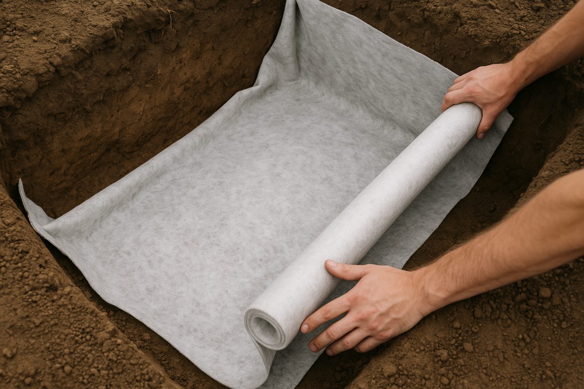
Geotextile rolled out Illustration -
3
Spread one layer.
Spread it a little thicker than the finished layer. With a light plate keep each layer to about 100 mm after compaction, with a heavy plate up to 150–200 mm.
Raking a layer to the pegs -
4
Dampen and compact.
Fill compacts best when damp, not dry and not wet. Go over the whole area two to four times, until the plate leaves no mark.
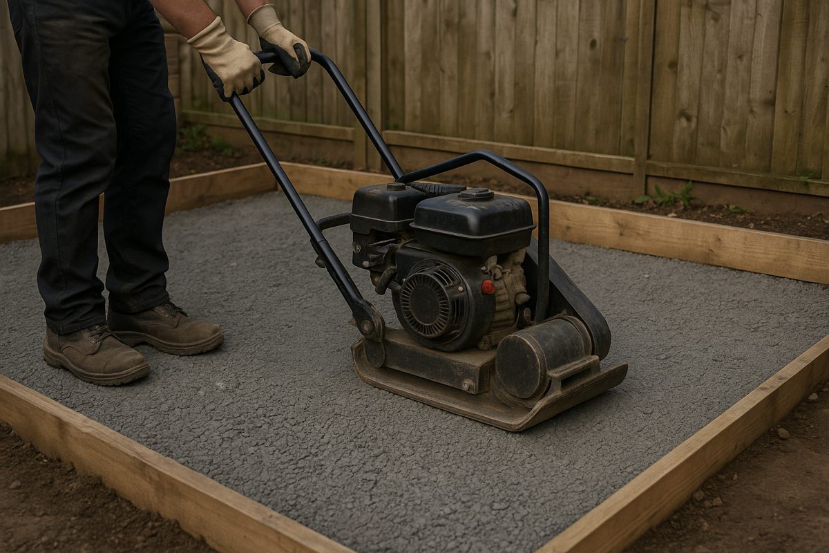
Plate compactor on the layer Illustration -
5
Check the level and repeat.
Check each layer against the pegs before the next. Stop at the underside of the base or capillary break that goes on top (chapters 3 and 6.1).
Checking level across the fill
Specifications
| Part | Sieve size | Thickness | How |
|---|---|---|---|
| 1 Subsoil | firm, undisturbed | – | Topsoil and soft pockets removed. |
| 2 Fill | 0–32 mm or 0–63 mm | layers of 100–200 mm | Damp, 2–4 passes per layer. 95 % of standard Proctor density where specified. |
Layer and compactor
Light plates compact about 100 mm of granular fill per layer, a rammer or mid-weight plate 150 mm, and the heaviest plates and rollers 200 mm. The US Bureau of Reclamation allows 150 mm with tampers and up to 300 mm only with heavy vibrators. Loose layers over about 300 mm stay loose at the bottom whatever the machine.
How firm
Specifications ask for 95 % of the standard Proctor density, tested to EN 13286-2 or ASTM D698. Without a test, compact until the surface no longer moves or marks under the plate.
Moisture
Fill compacts best close to its optimum water content. One road specification allows from 3 % below optimum up to optimum, a wall specification 2 % either side. Dry fill stays loose; wet fill turns soft.
Largest stone
Stones may be no more than half the layer thickness. With 0–63 mm, layers must be at least about 130 mm.
Sources
- US Bureau of Reclamation, Pipe bedding and backfill: compacted layers no more than 150 mm with tampers or rollers, up to 300 mm with surface vibrators on clean sand and gravel
- HAUC (UK), Specification for the reinstatement of openings in highways, compaction table: allowed layer thickness rises with compactor weight: lighter plates 100 mm, a 50 kg rammer up to 150 mm, the heaviest plates and rollers 200 mm
- US DOT research report, Equipment and lift thickness optimization for structure backfill: typical maximum loose lifts 150–300 mm; thicker lifts leave the bottom under-compacted; plates usually need two to four passes
- Iowa DOT Standard Specifications §2431, Segmental retaining wall: levelling pad at least 150 mm; backfill in layers of at most 200 mm at 95 % of standard Proctor density; only hand-operated compactors within 0.9 m of the wall face
- Texas State University construction standard 32 32 23.14, Segmental retaining wall: levelling pad of compacted sand and gravel at least 150 mm thick, reaching at least 150 mm in front of and behind the blocks; drainage stone clean and angular, all under 25 mm, at most 5 % passing 0.075 mm; backfill at 95 % of standard Proctor within 2 % of optimum moisture; hand-operated compactors only within 0.9 m
- Missouri S&T, GE 441 compaction lecture: thin layers with hand tampers, moisture near optimum, moisture control critical for silty soils
- Prince William County, Foundation backfill policy: no backfill until the concrete is strong enough (3 days above 23 °C, 7 days at 13–23 °C, 14 days at 4–13 °C); walls holding 1.2 m or more of fill anchored to the floor above or braced; no organic material or high-plasticity clay in the backfill
- EN 1610:2015 Construction and testing of drains and sewers: lower bedding at least 100 mm in usual soil and 150 mm in rock or hard soil (§7.2); minimum trench width OD + 0.40 m up to DN 225 (Table 1); stones in main backfill no bigger than half the compaction layer (§5)
- FHWA-RD-97-148, Granular base: natural aggregates weigh about 2.0–2.3 t/m³ in place
- EN 13242 Aggregates for unbound and hydraulically bound materials
- EN 13285 Unbound mixtures: specifications
- EN 13286-2 Unbound mixtures: Proctor compaction test (laboratory reference density)
Amounts: 1 m² × 100 mm = 0.1 m³ of compacted fill. Compacted crushed stone is taken as 2.1 t/m³, the middle of the 2.0–2.3 t/m³ range FHWA gives for natural aggregate in place. Order a little extra.
GLAREUM.NET · Aggregate Handbook